GAIN DEFINITIONS AND CIRCLES
Two port network gain can be defined as transducer power gain, operating power gain, and available power gain as follows:
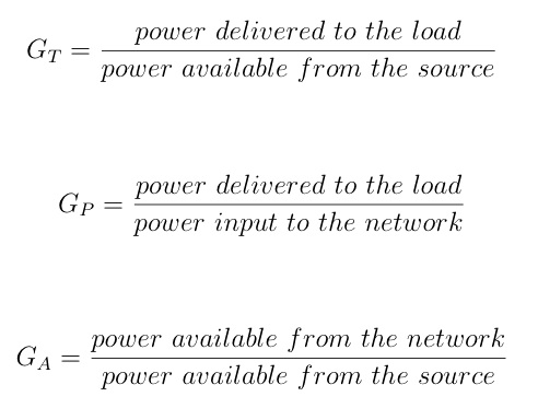
Expressions for these gains in terms of network parameters, and their derivations, can be found in the literature(1). They are given as:
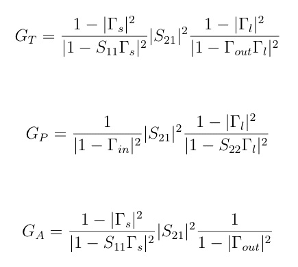
Practical high frequency transistor amplifier designs make use of the operating gain and the available gain procedures only. It's noted that the operating gain is a load plane quantity and is independant of the source impedance while the available gain is a source plane quantity and is independant of the load impedance. The transducer gain is a function of both source and load impedances. For high frequency devices the value of S12 is usually non-negligible so that a design procedure would be iterative and not very practical.
For given values of Ga and Gp the gain circles are defined as follows:
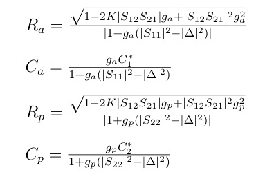
In this context Ga and Gp stand for the numeric gain value. R and C are the radius and center respectively of the corresponding gain circle plotted on the Smith Chart. Any source (load) reflection coefficient presented to the device and lying on the circle will yield a gain of the corresponding value.
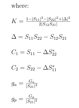
The noise figure can be expressed in terms of the source plane reflection coefficient and the noise parameters of noise resistance, minimum noise figure, and the source reflection coefficient resulting in the minimum noise figure. The noise parameters are given by the device manufacturer.
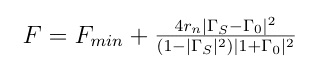
The noise circles are drawn on the Smith Chart using the following expressions:

(1) Microwave Transistor Amplifiers Analysis and Design, Guillermo Gonzalez, 1984, Prentice-Hall
Marcus Staloff
© 2013